- DC Power Supply for Industrial PC
- 4U PS2 ATX 2400W 470mm
- 4U PS2 ATX 2500W 450mm
- 4U PS2 ATX 1600W 370mm
- 4U PS2 ATX 1800W 350mm
- 4U PS2 ATX 1600W 320mm
- 4U PS2 ATX 1200W 270mm
- 4U PS2 ATX 1300W 255mm
- 4U PS2 ATX 1000W 225mm
- 4U PS2 ATX 1100W 200mm
- 4U PS2 ATX 1100W 184mm
- 4U PS2 ATX 1000W 170mm
- 4U PS2 ATX 700W 140mm
- 4U PC AT 450W
- 2U ATX 800W
- 1U ATX 850W 83mm width
- 1U ATX 750W 100mm width
- 1U ATX 920W 147mm width
- SFX DC to DC 660W
- Special size ATX 2700W
- DC PSU FANLESS
- DC PSU OPEN FRAME
- DC PSU SINGLE OUT
- DC PSU REDUNDANT
- Fanless Battery Charger
- Power Source Wire
STC News
Updated: 15/12/2025
12/2025. New Model of DC Input SFX Industrial Power Supplies with up to 660W output Power

Updated: 15/12/2025
12/2025. New Model of DC Input 2U PS2 ATX Industrial Power Supplies with up to 800W output Power
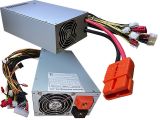
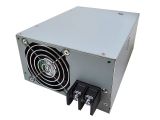
4U ±120V DC Industrial PC PS2 ATX Mini Redundant Power Supply

| Series | Model No. | Output Watts | Input Voltage | Input Voltage range | Polarity reverse protection |
| 120 | STC-120750RD | 750W continuous | ±120V DC
(Optional 110V AC) |
±85V ~ ±144V DC
(Optional 90V ~ 130V AC) |
Fuse protected |
| 120 | STC-120600RD | 600W continuous | ±120V DC
(Optional 110V AC) |
±85V ~ ±144V DC
(Optional 90V ~ 130V AC) |
Fuse protected |
| ENVIRONMENTAL CONDITIONS: | |
| ● Cooling: Forced Air Cooling, | 40x40x28 mm Fan x 2 (with 2 x Ball Bearing) |
| ● Fan brand: | DELTA, NMB, SUNON. Specifications are equivalent |
| ● Operating Temperature: | 0°C ~ +50°C Full Load |
| ● Output Power: | 100% @ 50°C, 70% @ 60°C |
| ● Operating Humidity: | 20%~85% RH. (Non condensing) (95% Optional) |
| ● Storage Temperature | -20°C~+80°C |
| ● Storage Humidity: | 10%~90% RH. (Non condensing) |
| ● Operating Altitude | 10M Below Sea level and 3000M Above Sea level |
| DC INPUT CHARACTERISTICS: | |
| ● Input connector type | 30A/300V UL Approved Gold Plated Brass 1.2t/2-Pin Terminal |
| ● Input Current | 5.2A/8.8A(600W) 6.14A/10.4A(750W) @ Full Load High Line & Low Line |
| ● Inrush Current | Less than 50A Cold start @25°C ambient |
| DC OUTPUT CHARACTERISTICS: | |
| Output Voltage | Regulation | Output Current | Ripple & Noise | |||||
| Load | Line | Cross | 750W | 600W | ||||
| Min | Max | Min | Max | |||||
| +5V | ±5% | ±1% | ±5% | 1A | 35A | 1A | 35A | 50mV |
| +12V | 1A | 50A | 1A | 40A | 120mV | |||
| +3.3V | 0.5A | 22A | 0.5A | 22A | 50mV | |||
| -12V | ±8% | 0A | 0.3A | 0A | 0.3A | 120mV | ||
| -5V (Optional) | ±5% | 0A | 0.5A | 0A | 0.5A | 50mV | ||
| +5VSB | ±5% | 0A | 3.5A | 0A | 3.5A | 50mV | ||
| Maximum continuous combined load on +3.3 V & +5V DC output shall not exceed | 175 | 175 | Watt | |||||
| Maximum continuous combined load on +3.3 V & +5V & +12V DC output shall not exceed | 720 | 570 | ||||||
| Maximum continuous total DC output power shall not exceed | 750 | 600 | ||||||
| OVERALL PERFORMANCE: | |
| ● Efficiency | 82% typical @120V DC Full Load |
| ● Hold up time | The output voltage stays regulated for at least 16ms with 100% load after loss of DC input |
| ● Rise time | The output voltage rise from 10% to 90% with full load shall be in 20ms maximum |
| ● Power Good Signal | TTL Compatible signal, on delay 100~500ms, off delay 1ms min |
| ● Short Circuit Protection (SCP) | All output equipped with SCP (shutdown and latch off) |
| ● Over Power Protection (OPP) | Peak power protected to 130%±10% of continuous rated power (shutdown and latch off) |
| ● Over Voltage Protection (OVP) | +3.3V@3.6V~4.3V, +5V@5.5V~6.5V, +12V@13.2V~15.6V |
| RELIABILITY: | |
| ● MTBF (Mean Time Between Failure): | 100 000 hours @max. Load, 120V DC & 25°C ambient |
| ● Safety Standards | Meet IEC 60950-1, EN 60950-1 |
| ● Safety Approved | |
| ● EMI Compatibility (EMC) Standard | EN 55032:2015/AC:2016, CISPR 32:2015, EN 6100-3-2:2014, |
| EN 6100-3-3:2013, EN 55024:2010 +A1:2015 | |
| ISOLATION:
|
|
| ● INPUT and OUTPUT are isolated by transformers and optical couplers | |
| ● Dielectric Withstand: | INPUT to OUTPUT: 2000V DC for 60 seconds |
| ● Dielectric Withstand: | INPUT to FRAME GROUND: 2000V DC for 60 seconds |
| ● Leakage Current: | <0.005μA @ 120V DC |
| LED Indicator: | |
| ● Power module 1: | Green LED when Power On |
| ● Power module 2: | Green LED when Power On |
| Alarm function: | |
| ● In the rear panel with power failure alarm signal to indicate when power failure wire | |
| Alarm reset switch: | |
| ● To reset by switch | |
| Output Connector specific: | |
| ● ATX 24 Pin x 1: | Molex 29-01-2240 or equivalent |
| ● +12V(P4) 4 pin x 1: | Molex 39-01-2040 or equivalent |
| ● HDD, DVD 4 pin x 4: | Molex 8981-04P or equivalent |
| ● FDD 4 pin x 1: | AMP 171822-4 or equivalent |
| ● Serial ATA x 2: | Molex 675820000 or equivalent |
| ● CPU EPS 8 Pins x 1: | Molex 39-01-2080 or equivalent |
| ● PCIe x 2 | / STC-120600RD |
| ● PCIe x 3 | / STC-120750RD |
| Standard Output Cable Length: | |
| ● 500 mm / 19.68 inches | |
| PCB specific: | |
| ● 4 layer | |
| ● Copper: 3 Oz each layer | |
| ● Thickness: 1.6 mm | |
| ● Material: FR4 | |
| ● PCB material origin: Taiwan | |
| Power chassis Dimension: | |
| ● 225(L) x 150(W) x 86(H) mm / 8.86(L) x 5.9(W) x 3.39(H) Inches | |
| Rackmount chassis solution: | |
| ● 4U IPC Chassis 510mm Model no. GHI419ATX | |
| Screw hole: | |
| ● Front Panel with 4 screw holes | |
| ● Rear panel bracket with 2 screw holes | |
| Net Weight: | |
| ● 4.8 kg / 10.85 lbs | |
| Gross Weight: | |
| ● 6 kg / 13.22 lbs | |
| Packing Detail | |
| ● 2 pcs | |
| ● 12 kg / 26.45 lbs | |
| Measurement of Carton | |
| ● 0.045 m3 / 1.59 Cuft | |
| Note | |
| ● Power Supply is not able to be used in stand alone application | |
| ● Use Power Supply in Power Chassis Assembly only | |
 DOWNLOAD_specification_RD_STC-120750RD DOWNLOAD_alarm_diagram_STC-xxx00RD DOWNLOAD_stc-12400rd_stc-24500rd_stc-48600rd_stc-48750rd.(stc-ps2-rd-225)-20230331-1.pdf